Create a Bouncing Coin Effect Using Colliders
Use colliders to generate an effect where coins bounce off of your head in the Visual Effects (VFX) Editor.

Set Up Your VFX Environment
After you've created a new project in Effect House, you will need to set up a VFX environment. You can utilize one of the two methods outlined below. For more information on the VFX Editor, check out the VFX Editor Overview.
Method 1
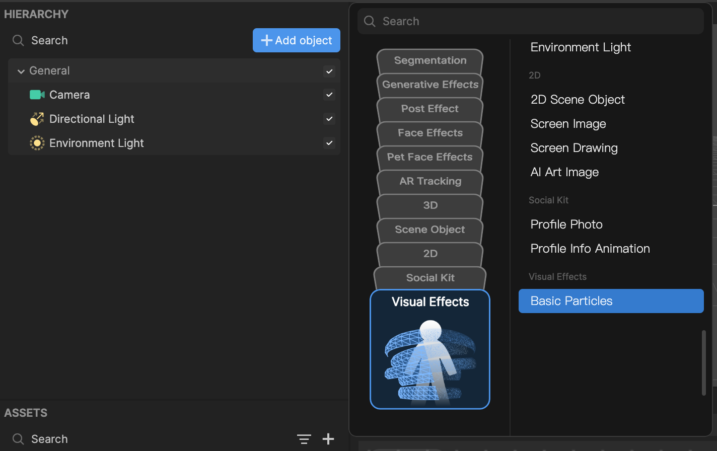
- Go to the Hierarchy panel
- Click the Add object button [+]
- Go to Visual Effects
- Select Basic Particles
Method 2
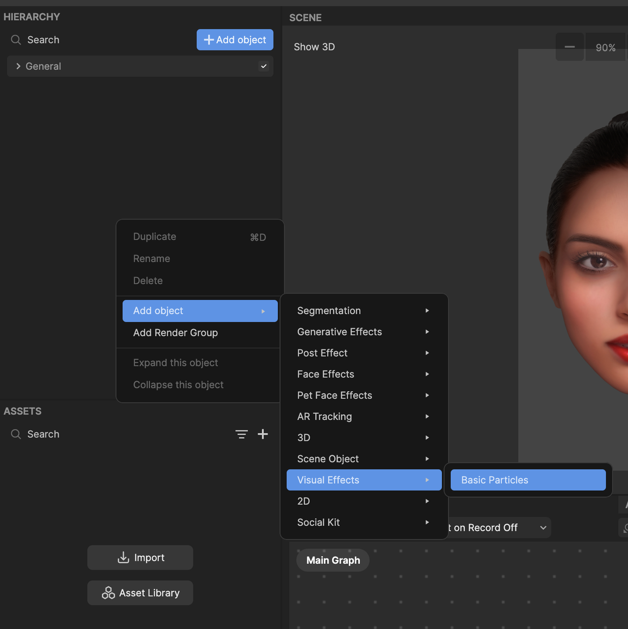
- Go to the Hierarchy panel
- Right click on the panel to view the menu popup window
- Navigate to Add object
- Go to Visual Effects
- Select Basic Particles
Once you've added the Basic Particles object, you will see the Visual Effect Graph. You should also notice white particles moving in the Preview panel.
To see your changes immediately as you make them, enable the Auto Compile option by clicking the Auto Compile button. If this option is not enabled, you’ll need to manually click the Compile button after each update to view your changes.
Import a 2D Texture
You will need a 2D spritesheet texture asset for the effect. Import the following file to get started:
To import a 2D texture asset:
- Go to the Assets panel
- Click the Add asset button [+]
- Go to Import and click From Computer
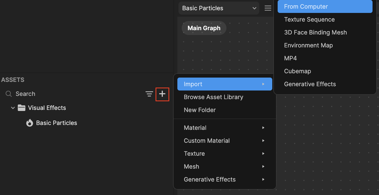
- Select and import the image that was included in the zip file
Colliders in the VFX Editor
There are a total of 5 colliders available:
- Collide With Box
- Collide With Capsule
- Collide With Plane
- Collide With SDF
- Collide With Sphere
In this demonstration, we will be using Collide With Capsule.
Let's dive into what each parameter does.
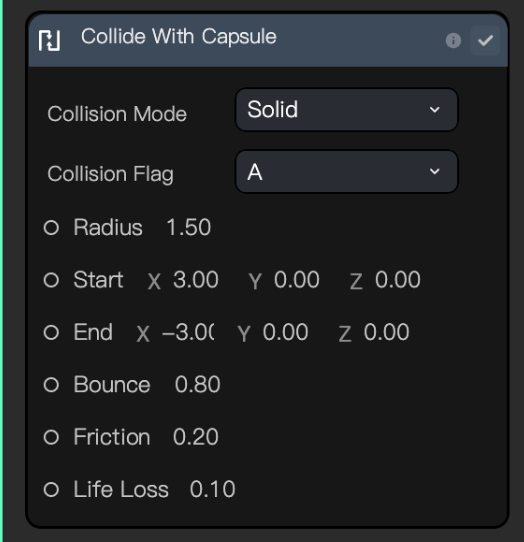
Collision Mode
Solid: Collides based on the outer surface

Inverted: Collides based on the inner surface

Collision Flag
Collision Flag comes with flags A to H. By setting a specific flag type, the system can retrieve the collision status of the particle, whether it collides with that specific flagged collider or not (boolean).
For the example below, if Get Collision Status with Collision Flag A is true, we will return the red color. Otherwise, we will return the blue color.
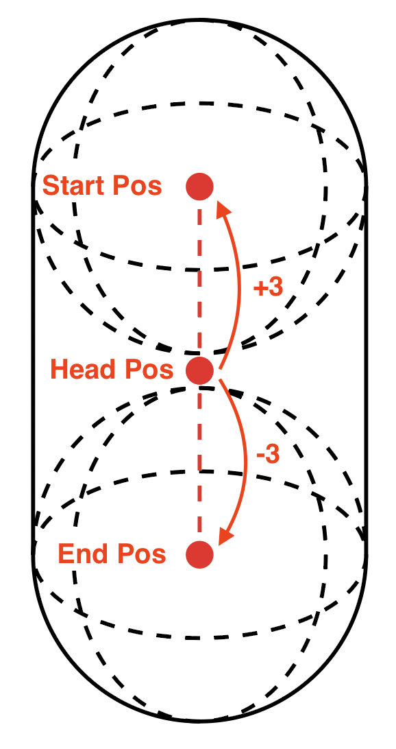
When Collide With Capsule is added to the node, it creates a shape based on the radius, start, and end positions, as shown in the diagram below.
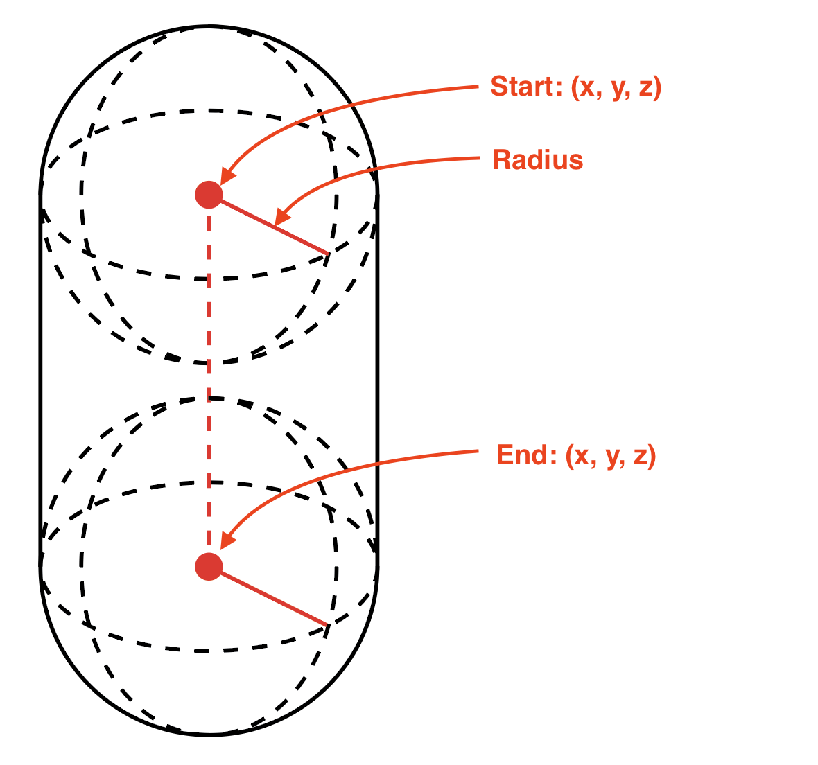
Radius
The radius of the 3D capsule shape.
Radius: 1.0
Radius: 2.0
Radius: 3.0
Start
The starting position (x,y,z) of the 3D capsule shape.
End
The ending position (x,y,z) of the 3D capsule shape.
Start: (0.0, 5.0, 0.0), End: (0.0, -2.0, 0.0)
Start: (0.0, 5.0, 0.0), End: (2.0, 0.0, 0.0)
Start: (0.0, 5.0, 0.0), End: (2.0, 0.0, 5.0)*
*Because End's Z position is 5.0 (closer to the camera), the collision happens later, towards to the bottom of the capsule collider.
Bounce
The amount of bounce applied to the particles after collision.


Bounce: 0
Bounce: 0.5
Bounce: 1
Friction
The velocity the particles lose after collision.


Bounce: 0
Bounce: 0.5
Bounce: 1
Life Loss
The age that the particles lose after collision (normalized 0-1).


Bounce: 0
Bounce: 0.5
Bounce: 1
Initial Set Up
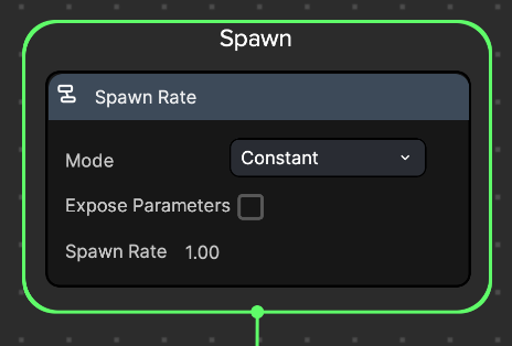
In the Spawn logic, change Spawn Rate to 1.00.
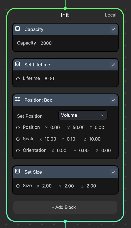
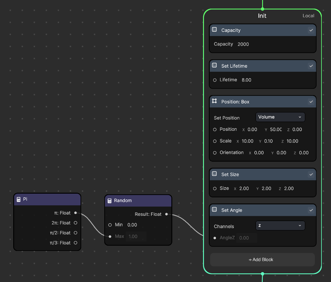
In the Init logic:
- Delete the Set Random Velocity node
- Change Set Lifetime to 8
- Add a Position: Box node and set the Position: (0, 50, 0) and Scale: (10, 0.1, 10). This maintains the particle's spawn location within a box shaped area.
- Setting the position to (0, 50, 0) allows the particles to be spawned from the top of the screen
- Setting the scale to (10, 0.1, 10) creates an invisible, horizontally aligned rectangular box where particles will be spawned within
- Add a Set Size node and set the Size: (2, 2, 2). This will assign each particle a specific size.
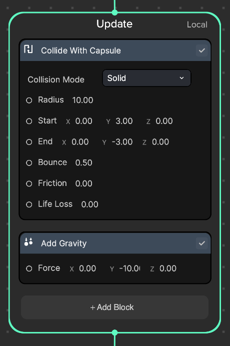
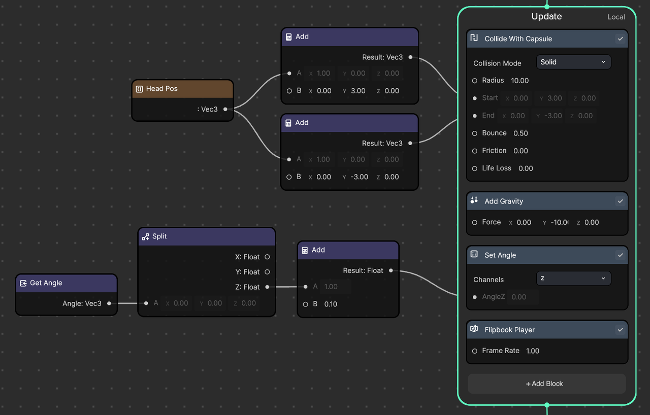
In the Update logic:
- Add a Collide With Capsule node and set each of its properties to the following:
- Collision Mode: Solid
- Radius: 10
- Start: (0, 3, 0)
- End: (0, -3, 0)
- Bounce: 0.5
- Friction: 0
- Life Loss: 0
- Add an Add Gravity node and set Force: (0, -10, 0). This will create a falling down motion.
For now, keep the Output logic at its default setting.
The particles should now fall from the top of the screen individually and bounce off after colliding with the invisible capsule collider.

Move the Capsule Collider using Head Tracker
To make this effect more interactive, let's link the capsule collider's position to a Head Tracker component so that the particles can collide with the head.
To add a Head Tracker component:
- Go to the Hierarchy panel
- Click the Add object button [+]
- Go to AR Tracking
- Select Head Tracker
You should see a Head Tracker object with its respective Head mesh added to the Hierarchy panel.
Now, we need the capsule collider that we created in the Visual Effect Graph panel to follow the head's position. This can be done in the Visual Scripting panel. But, in order to access the Visual Effects Graph panel from the Visual Scripting panel, we'll need to create a parameter in the Visual Effects Graph panel.
- Go to the Visual Effect Graph panel
- Click the My Items menu
- Go to Parameters and click [+]
- Select Vector3f. This will create a Vec3 (x, y, z) parameter.
- Rename Vector3f to Head Pos
- Click the small white circle next to Head Pos to create a node
In the Update logic:
- Create two Add operator nodes
- Connect one Add node to the Start input port and the other Add node to the End input port of the Collide with Capsule node
- Connect the Head Pos node to the A input port for both Add nodes
- Set B to (0, 3, 0) in the first Add node and set B to (0, -3, 0) in the second Add node, respectively. This adds and subtracts 3 on the y-axis to get the offset from the Head Pos node.
You'll need to import the Set Head Pos parameter from the Visual Effect Graph panel to the Visual Scripting panel. Make sure you are in the Visual Scripting panel, or the parameter will not be imported.
- Go to the Assets panel
- Click Basic Particles
- Go to the Inspector panel
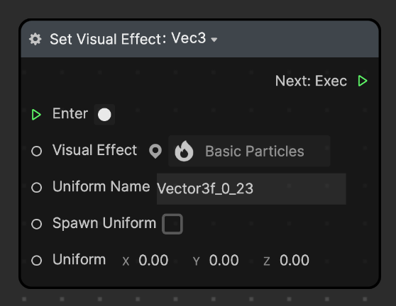
- Click on the small white dot in front of Head Pos and click Set Head Pos
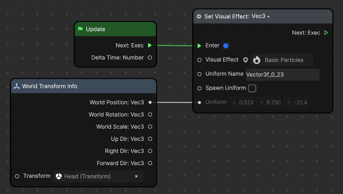
You should see the Set Visual Effect: Vec3 node appear in the Visual Scripting panel.
Now, we'll need the original head mesh's position information, so that we can pass it onto the Head Pos node in the Visual Effect Graph panel.
- Go to the Visual Scripting panel
- Right-click on the panel and click Add node
- Search for World Transform Info, then click on it to create the node
- Go to the World Transform Info node
- Go to Transform and click None (a pop up window will appear)
- Select Head (mesh) and click Ok
- Connect the Update and World Transform Info nodes to the Set Visual Effect: Vec3 (Head Pos) node as shown in the screenshot below. This will pass the Head Mesh position value to the Head Pos parameter in the Visual Effect Graph panel in each frame.
- Now, you can see the capsule collider following the head tracker and the particles bouncing off the head.

Final Touches
In the Init logic:
- Add a Set Angle block node
- In Set Angle, change Channels to z. This will accept inputs for angles on the z-axis.
- Add the Pi and Random operator nodes
- Connect Pi (π) to Random (Max) and Random to Set Angle. This will give each particle an angle between 0 to 180°.
In the Update logic:
- Add the Set Angle and Flipbook Player block nodes
- In Set Angle, change Channels to z. This will accept inputs for angles on the z-axis.
- In Flipbook Player, set Frame Rate: 1. This is the number of flipbook textures (spritesheet) played in 1 second. In this case, it will play one image per second.
- Add the Get Angle, Split, and Add operator nodes
- Connect Get Angle to Split, Split to Add, and Add to Set Angle, as shown below
- Set B to 0.1 in the Add node
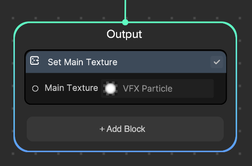
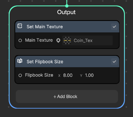
In the Output logic:
- In Set Main Texture, change Main Texture to Coin_Tex (the 2D image we previously imported)
- Add the Set Flipbook Size node and set Flipbook Size to (8, 1). This is because the Coin_Tex image contains 8 columns (x) with 1 row (y).
You should now see the rotating coins falling down and colliding with your head. You'll also notice that the texture looks washed out and has a bit of transparency. This happens because we are using Additive blend mode by default. Let's fix this.

To change the Blend Mode:
- Go to the Visual Effect Graph panel
- Click the Details button [i]
- Click the Output context node (a setting window will pop up in the details panel on the right)
- Go to Blend Mode and choose Alpha
There you have it! Make sure to try out the other colliders and collision modes to expand your VFX Effects.